Electrical Motor Controls

Course Description:
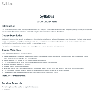
This course, developed by Bridgerland Technical College, teaches students about electrical symbols and schematics. In the course, students use wiring diagrams and schematics to wire basic and advanced control circuits. Students also design, simulate, and wire circuits that include control relays, timing relays, and motor starters. Upon completing the course, students should be able to:
- identify the working characteristics of basic electrical motor control devices such as: push buttons, selector switches, over current devices, control relays, overload devices, contactors, and overload blocks,
- identify ANSI electrical symbols for basic electrical motor control devices,
- use ANSI symbols to design, install, and troubleshoot basic electrical motor control systems,
- read and draw wiring diagrams and schematics,
- wire and operate circuits from schematics,
- wire basic control circuits such as power, reversing, interlocking, plugging, inching, timing, and automatic starting circuits from schematics,
- use line diagrams, schematic drawings, and test equipment to isolate problems in basic electrical control systems,
- follow a step-by-step troubleshooting process to solve problems within an integrated system.
Course Contents:
Course materials include a Canvas .imscc file. The .imscc file includes numerous folders and files from the Canvas course, including a syllabus. The syllabus includes a course description, course objectives, and instructor and grading information.
This course includes seven modules. Most modules include an introduction video and labs.
Below is a sample of modules and labs included in this course:
- Module 1: Introduction to Motor Controls, 6 hrs
- Overview
- Switching From AC to DC
- Kit Parts List
- Introduction to Your Trainer
- Lab 1-1: First Circuit
- Lab 1-2: Second Circuit
- Lab 1-3: Introduction to Motor Starters
- Module 2: Control Logic, 8 hrs
- Overview
- Control Logic
- Lab 2-1: The "AND" Circuit
- Lab 2-2: The "OR" Circuit
- Lab 2-3: The "AND/OR" Circuit
- Lab 2-4: The "NOT" Circuit
- Lab 2-5: The "NOR" Circuit
- Lab 2-6: The "NAND" Circuit
- Lab 2-7: Design and Build a Circuit
- Module 3: Common Control Circuits, 20 hrs
- Overview
- Motor Starters and the Typical Motor Control Circuit
- Lab 3-1: A Look at the Power Circuit
- Lab 3-2: Build a Typical Motor Control Circuit
- Automation Studio: Demo of Typical Motor Control Circuit
- Lab 3-3: Typical Motor Control Circuit with Two Start/Stops
- Lab 3-4: Motor Control Circuit with Permission
- Lab 3-5: Motor Control Circuit with Indicator Light
- Lab 3-6: Design and Build a Motor Control Circuit With Two Indicators
- Lab 3-7: Automatic Control Using a Pressure Switch
- Lab 3-8: Two Start/Stop Stations and Two Motors Wih a Shared E-Stop
- Lab 3-9: Two Motors, Simultaneous Start
- Lab 3-10: Design a Control Circuit for Three Conveyors
- Lab 3-11: Design and Build a Run/Jog Circuit
- Module 4: Control Relays and Timing Relays, 20 hrs
- Overview
- Control Relays
- Diagrams of the Control Relays on the Trainer
- Lab 4-1: Using a Control Relay
- Lab 4-2: Control Relay as a Master Control Relay
- Lab 4-3: Using a Timing Relay
- Lab 4-4: Using a Timing Relay, Part 2
- Lab 4-5: Second Motor, Delayed Start
- Lab 4-6: Filling a Grain Bin
- Lab 4-7: Design and Build a Pre-Start Alarm, Then a Start Motor
- Module 5: Reversing, 8 hrs
- Overview
- Lab 5-1: Complete Motor Circuit, Power, and Control
- AC Motors and Reversing
- Lab 5-2: First Reversing Circuit
- Lab 5-3: Typical Reversing Circuit
- Lab 5-4: Use a Limit Switch to Provide Automatic Reversing
- Lab 5-5: Design and Build a Selectable Forward/Reverse Circuit
- Module 6: Two Final Projects, 8 hrs
- Overview
- Lab 6-1: Design and Build, Project 1
- Lab 6-2: Design and Build, Project 2
- Module 7: Troubleshooting Control Circuits, 19 hrs
- Overview
- Simutech - Troubleshooting Control Circuits
- Basic Level Troubleshooting
- Intermediate Level Troubleshooting
- Advanced Level Troubleshooting
- Certificate of Completion
About this Resource

Comments